Altox-VW-Touareg
Report from our customer on the installation of the Altox Wbus-4 GSM module to control Webasto module in Volkswagen Touareg GP

This photo report covers the upgrade and revamp of the default Webasto auxiliary heater for a Volkswagen Touareg GP into a full-featured starting pre-heater.
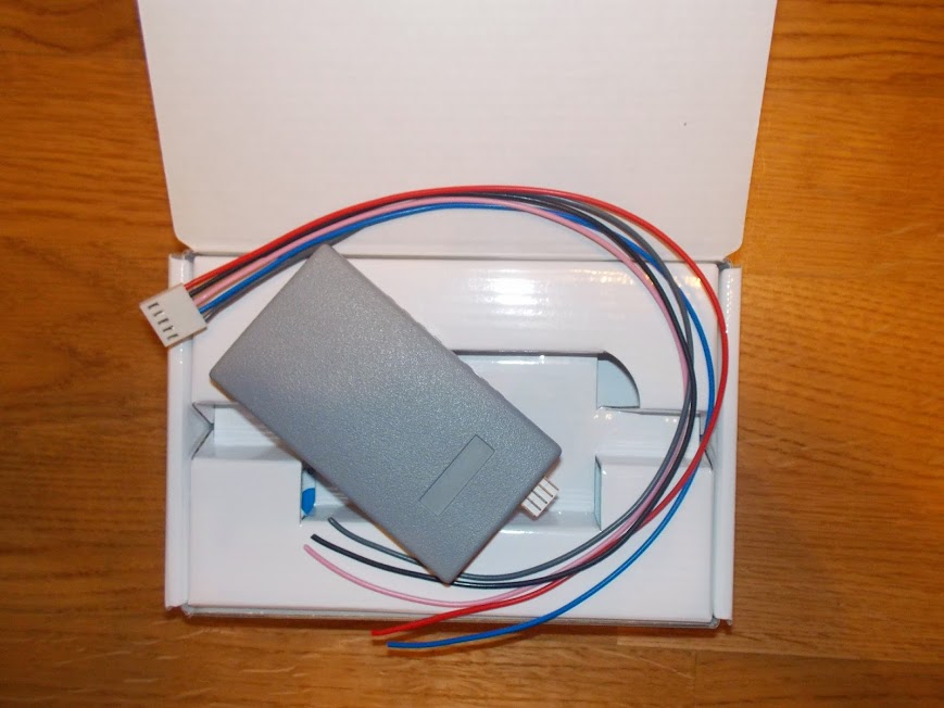

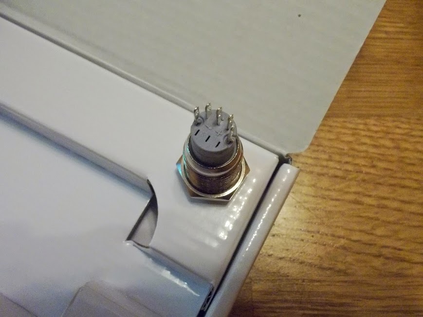
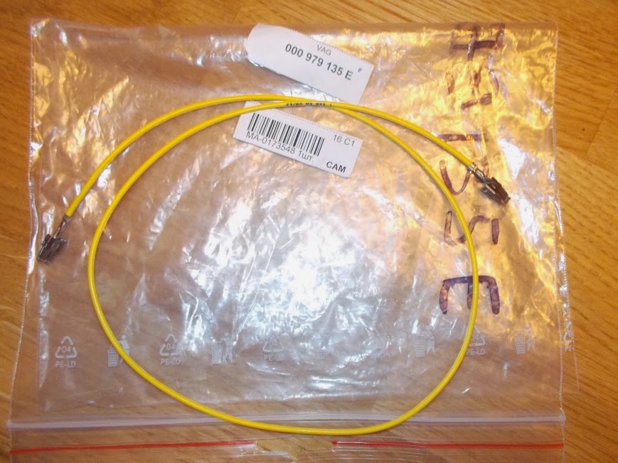

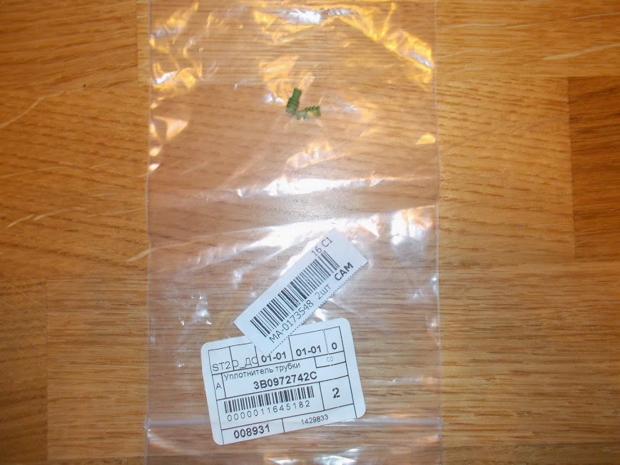
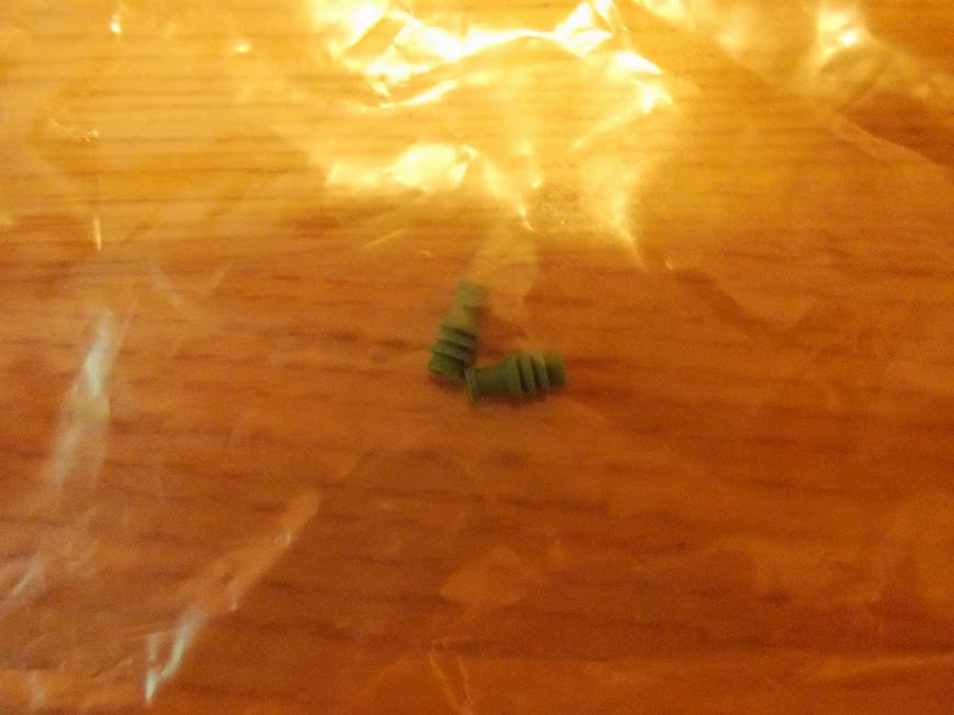
For the purpose of the installation, the following equipment has been purchased:- Altox WBUS-4 GSM module;- Non-latching button for the forced switching on/off of Webasto module;- Cable to connect the fuse in the fuse panel - 000 979 135E (the cable is to be cut in half, one part with the cable connector is used for the installation);- Cable to connect to the Webasto module – 000 979 009E (the cable is to be cut in half, one part with the cable connector is used for the installation);- Rubber seals for contacts in the Webasto connector 3B0 972 742C.
Let's start assembling. Remove the plastic cover on the left hand side. Pick it up from below.
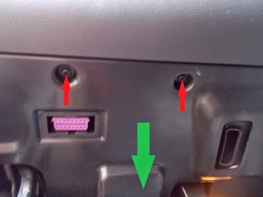
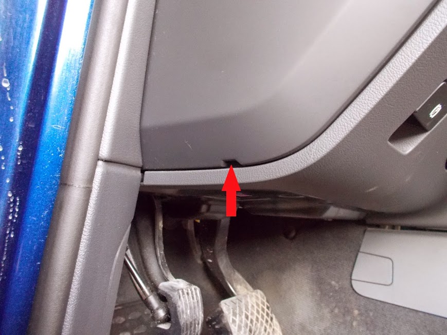
Remove the lower plastic cover under the steering wheel, unscrew two screws and pull the cover down. Click off and remove the diagnostic outlet.
Remove the lighting outlet by clasping whiskers on the sides.

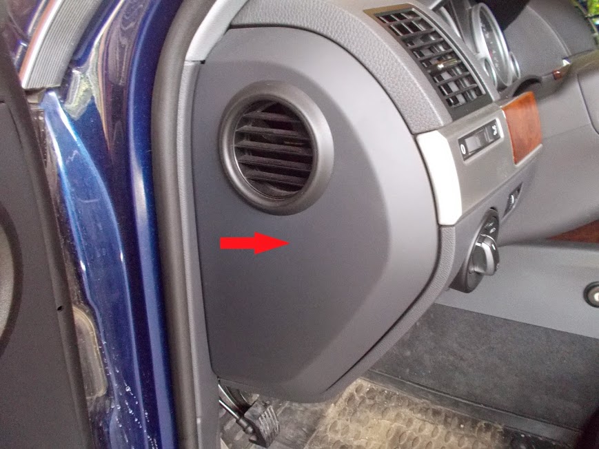
Then remove the cover on the left side of the steering wheel, unscrew the screw on the left hand side.
Then gently pull forward and remove the decorative cover to the left from the steering wheel.
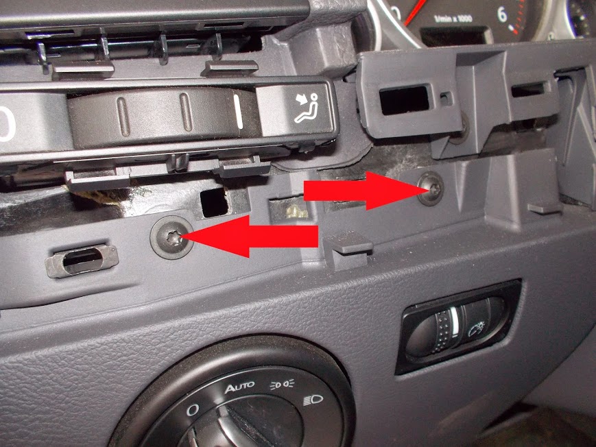
Under this cover you will see two screws. Unscrew them.
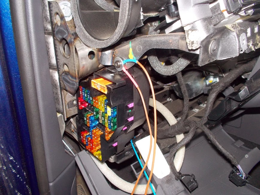
Pull forward a bit and remove the cover, pull out sound insulation from around the fuse panel.
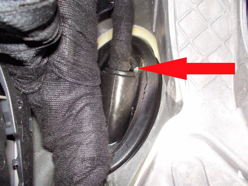
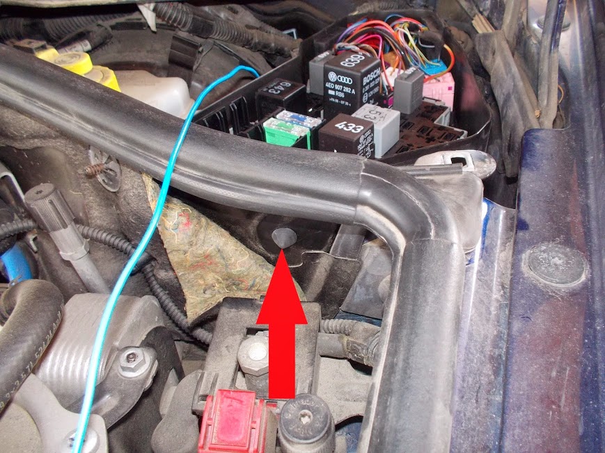
Get under the steering wheel and you will see a plug. I drilled a hole there.
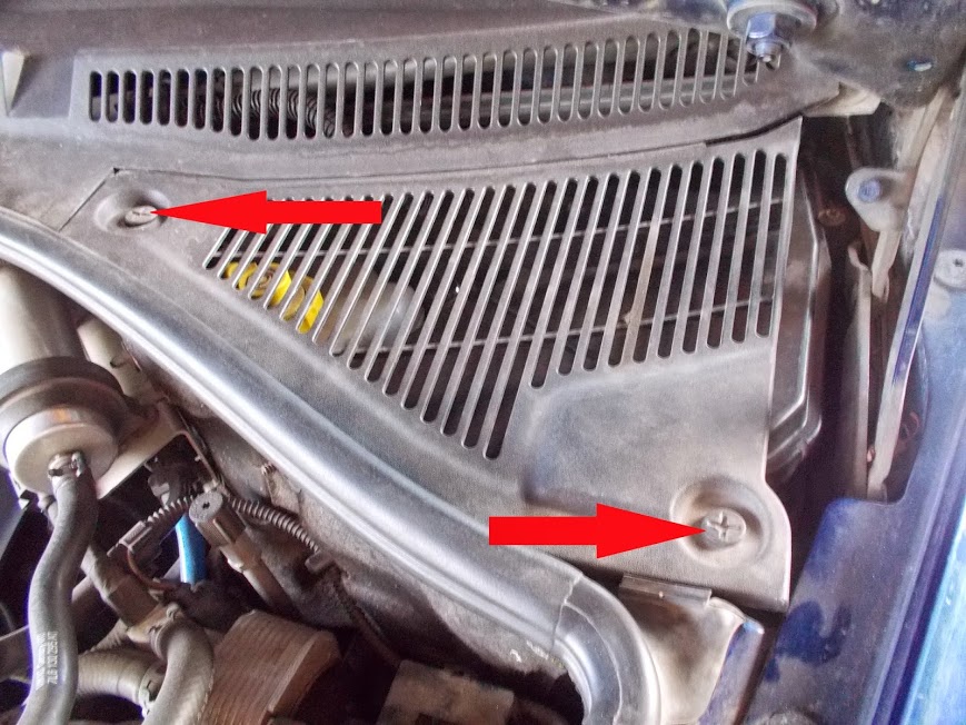
Open the hood and remove the grid from the right side. There are two screws. Unscrew then counterclockwise.

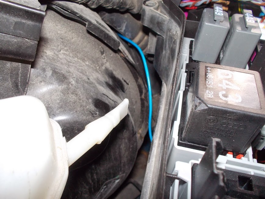
I removed the cover from relays unit and fuses by unscrewing four mounting screws. That provides a better visibility for the cable that is pulled from the car's interior.
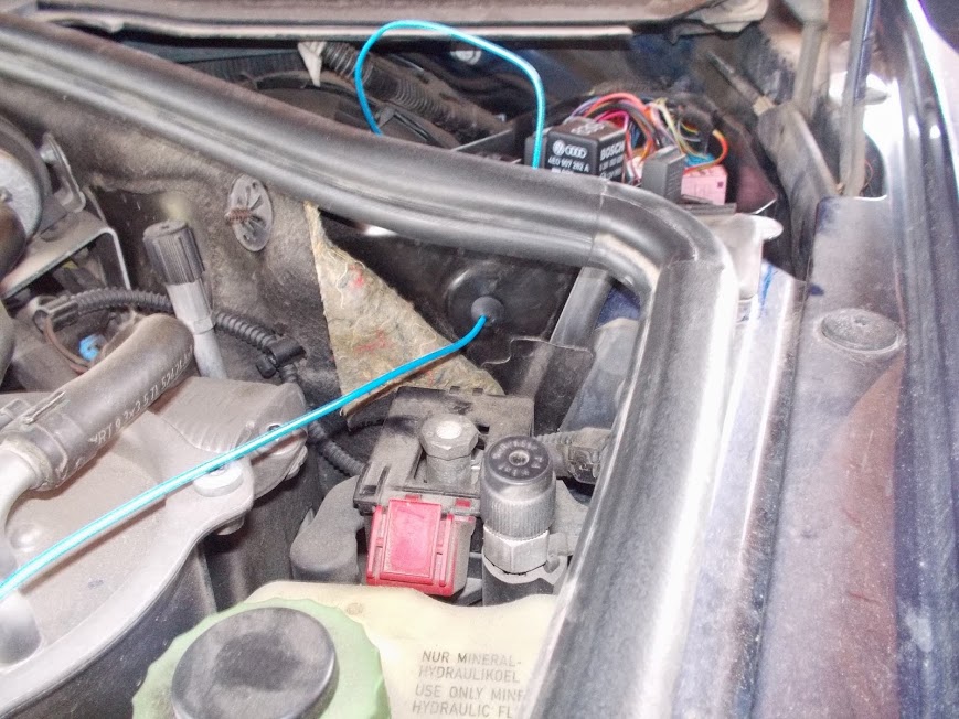
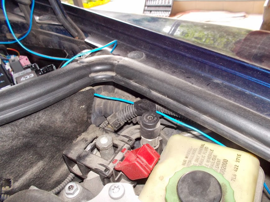
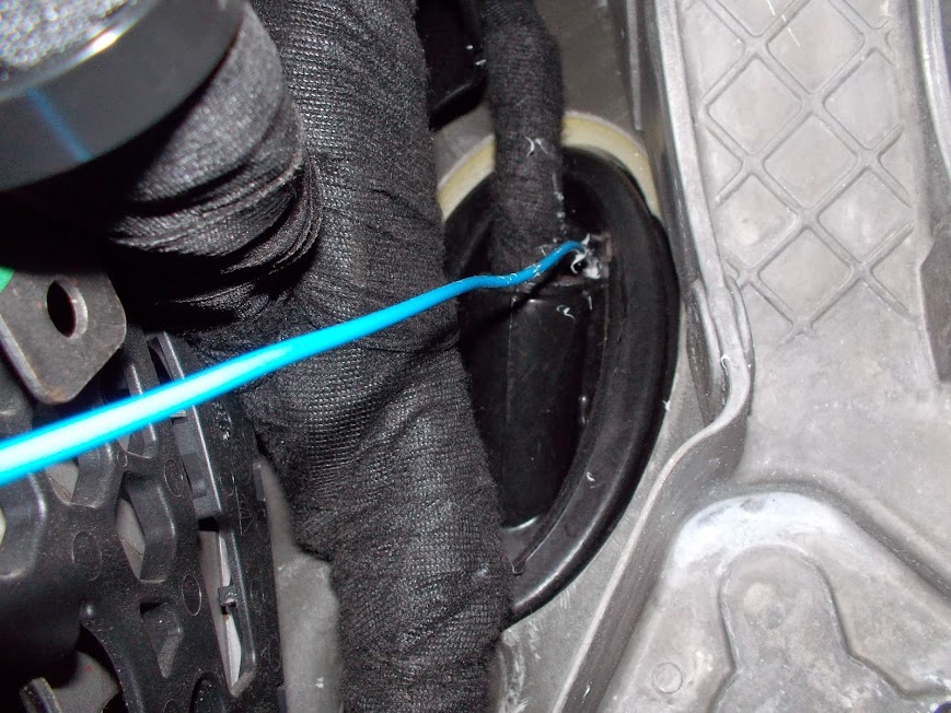
Pull the cable through the hole you drilled in the plug. To make it easier, I took a thin wire, tied it to the cable and pulled it through.
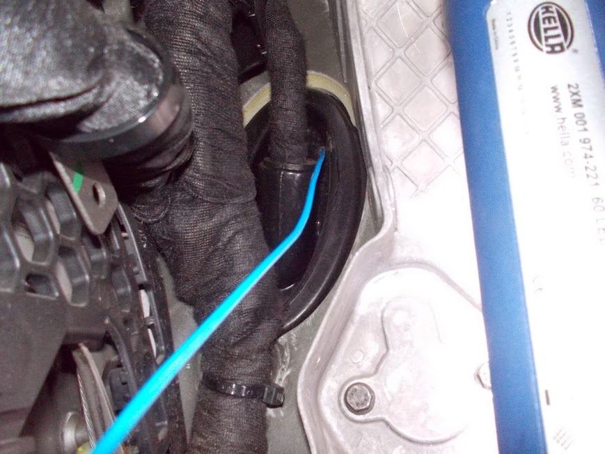
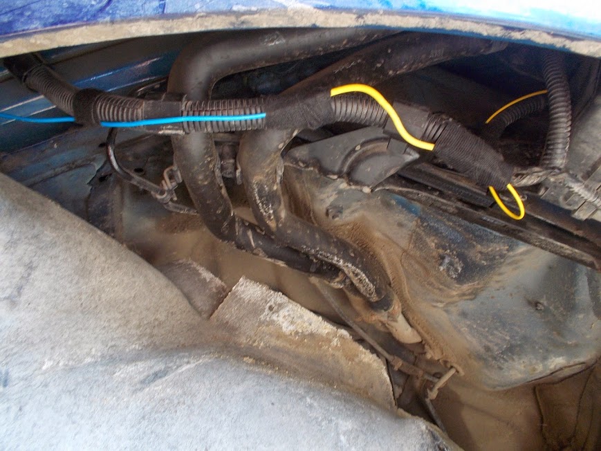
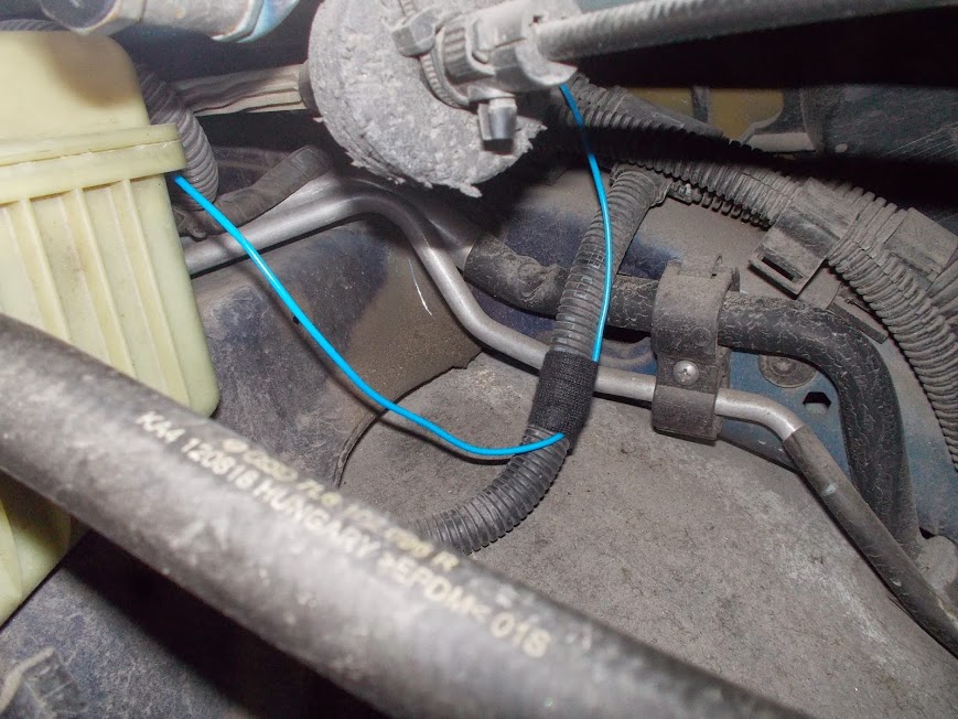
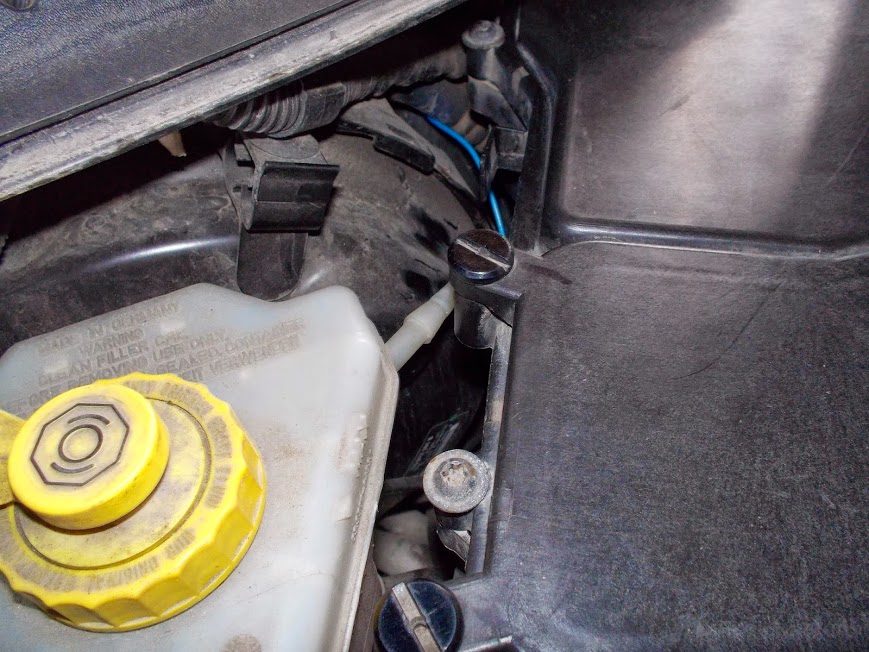
The cable will get through and be out to the right hand side from the vacuum booster.
To connect the cable to the engine compartment I used a rubber plug.I drilled a hole in there and pull the cable through.

Now we need to get to the Webasto module. To do this, we put the car up on the driver's side, remove the wheel, unscrew the wheel arch cover. To do that, we unscrew six mounting screws of the splash guard.
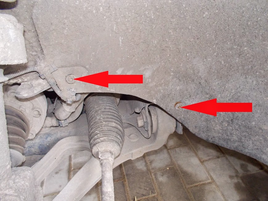
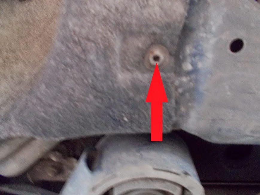
Then unscrew two screws in the area of the drive.
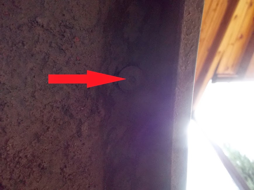
Unscrew the plastic cap at the top.


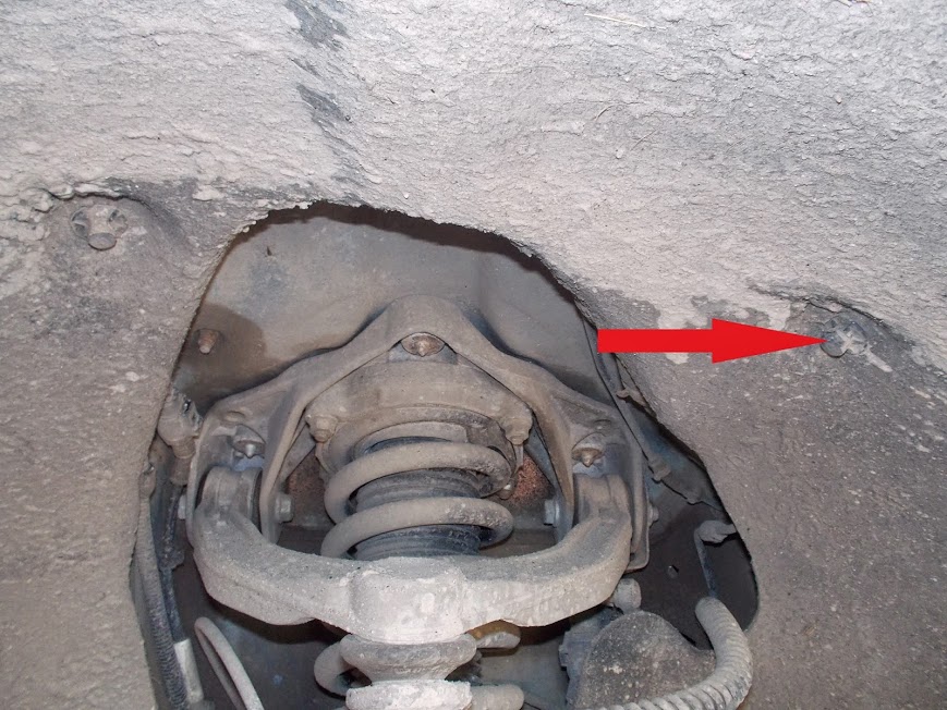
Unscrew three mounting screws of the wheel arch cover around the circumference.
Finally, unscrew one more screw down on the right hand side of the wheel.
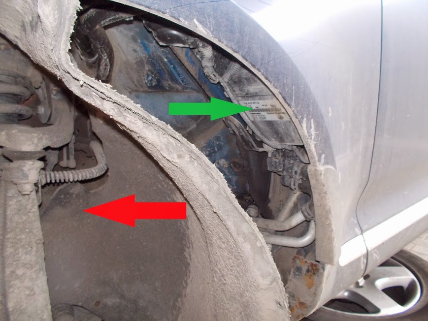
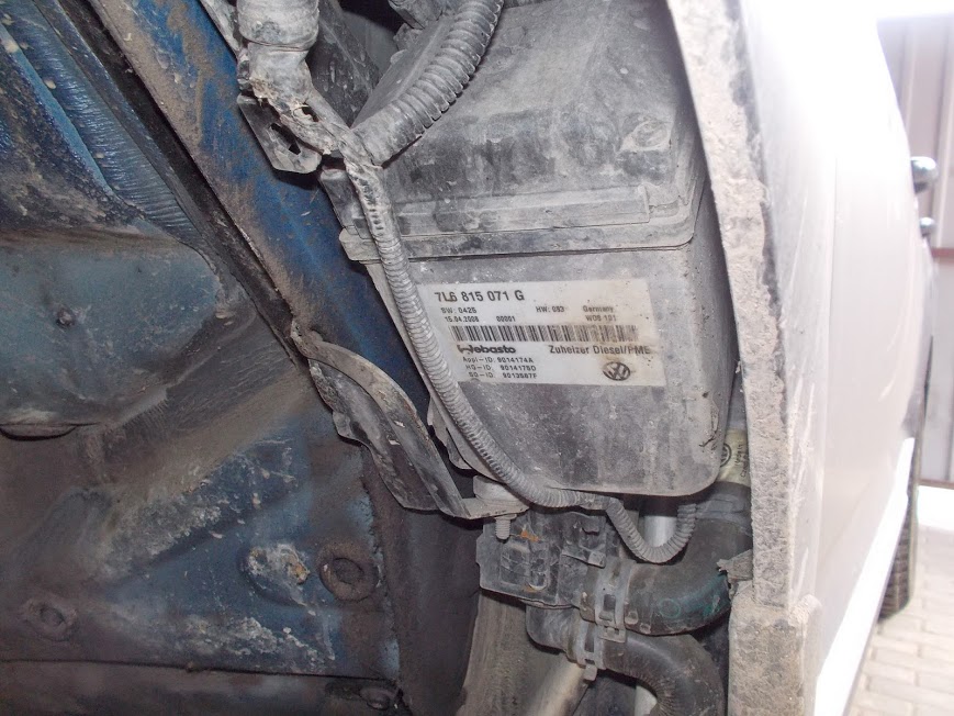
Pull the wheel arch cover to the brake rotor and you will see the Webasto module.
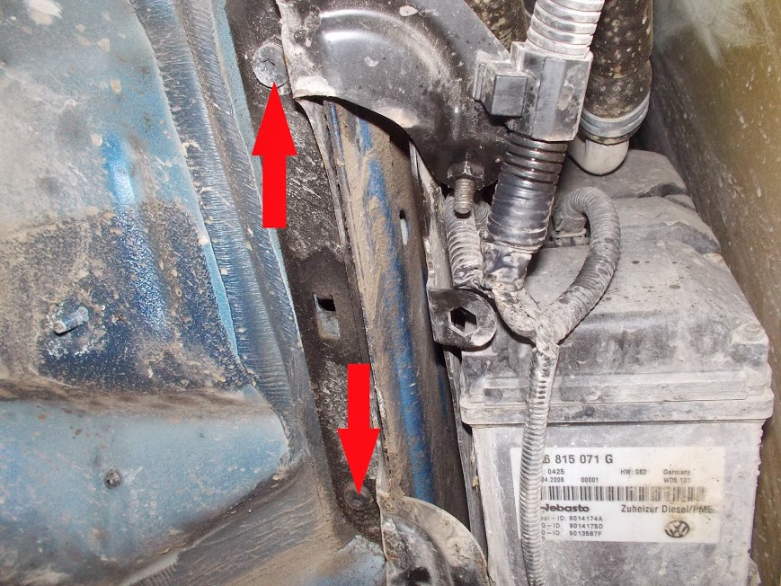
To make it easier to access the Webasto outlets (we need the 6-pin outlet on the left); unscrew mounting screws of the Webasto bracket.
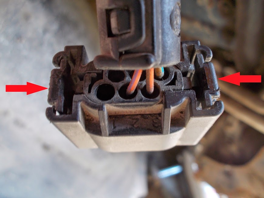
Pull the bracket gently towards yourself as much as you can. To remove the outlet clasp the side latches.
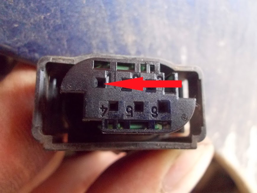
In the outlet we need contact no. 1.
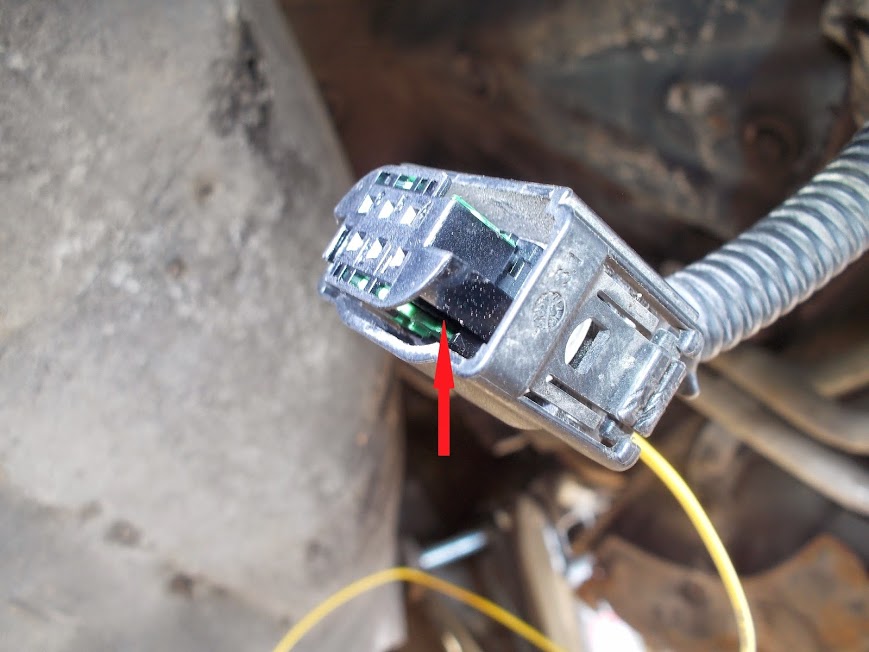
Remove the rubber plug from there (I screwed in the self-tapping screw of the suitable diameter into the plug and then pulled it out), and put inside the cable you purchased for the Webasto module (000 979 009E). To do that, I had to pull the green part of the outlet to the side using a thin screwdriver. Otherwise, the contact just did not get into place.

Then put rubber seals (3B0 972 742C) on the cable and using a thin screwdriver push it into the outlet.
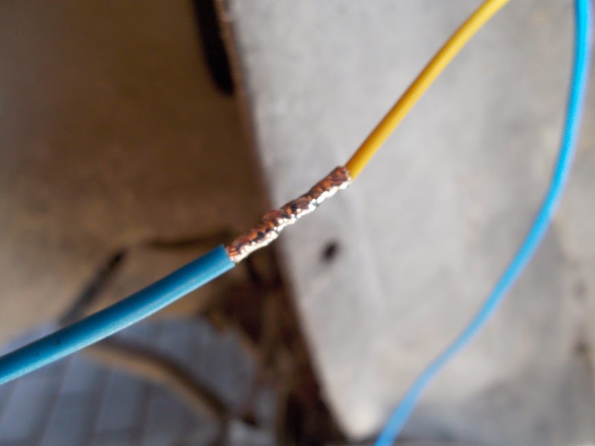
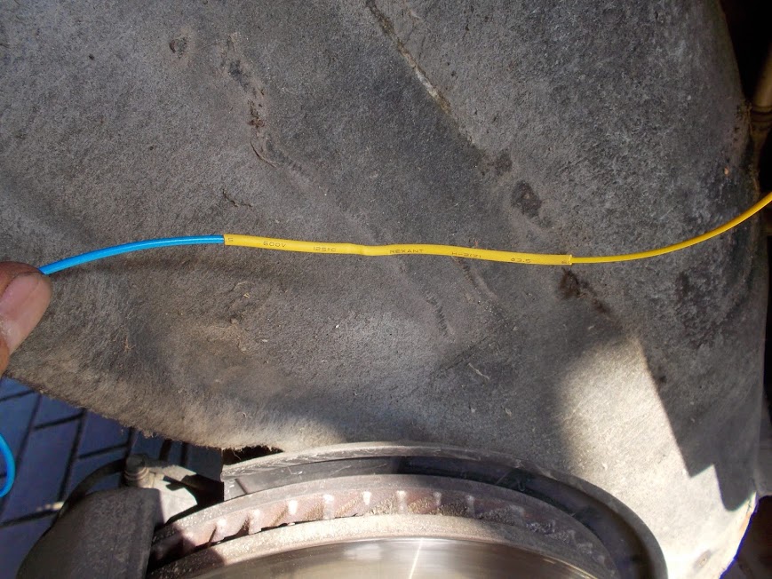
The cable that was pulled to the engine compartment, then it was pulled through the splasher, reached the Webasto module. Finally, it was soldered to the cable with the outlet, and the brazing joint was covered with a thermal contraction tube.
Put the outlet back in place, screw the bracket back in, secure the cable along the harnesses with the electrical tape.
Remove the excesses cable by pulling it back into the car's interior and close the relays unit and fuse panel cover under the hood. I pulled the cable around this unit.
The place where the cable was put through the plug should be filled in with joint sealer.
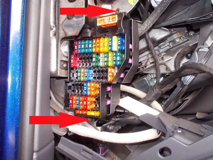
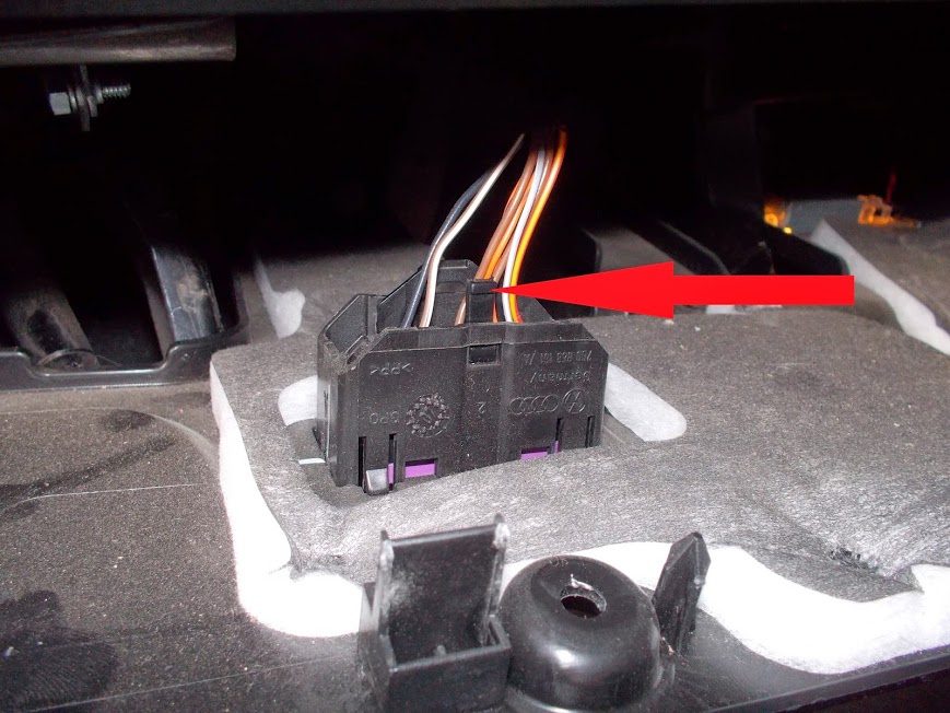
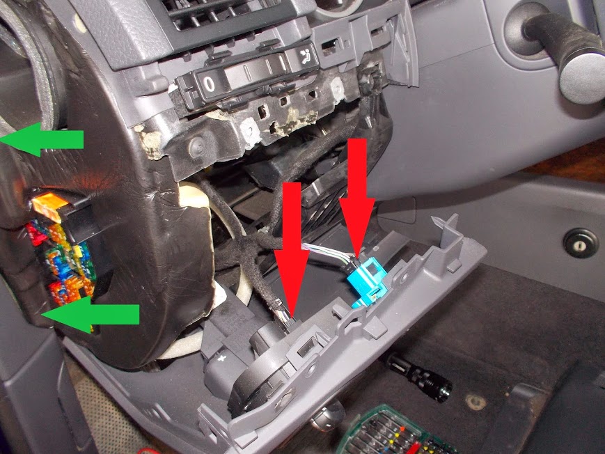
Now, let's move to works in the car's interior.To supply + 12V to the Altox WBUS-4 GSM module and the button, we connect the cable for the fuse (000 979 135E) to the socket. First, unscrew two mounting screws of the unit and remove it.
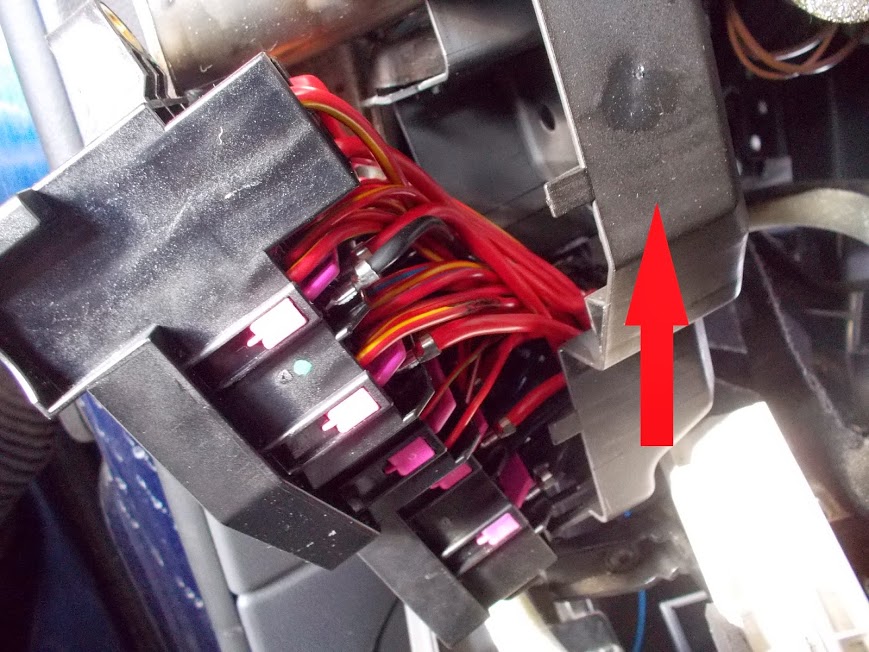
Then, unlatch and remove the backside cover of the unit.
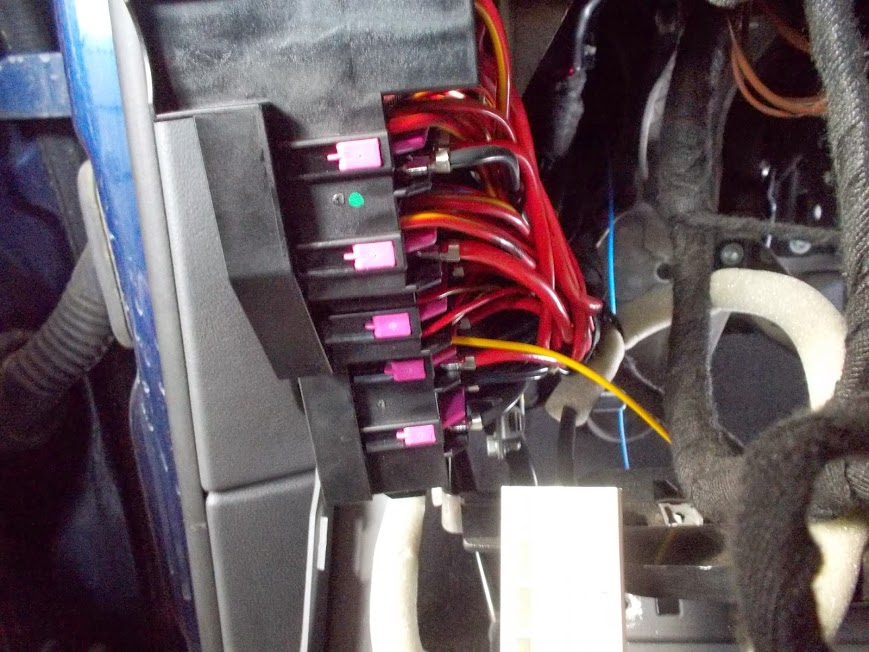
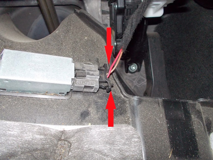
Insert the outlet for the fuse inside the unit, center it vertically in the cell, otherwise it will not close.

The fuse will stay here.
The minus wire for the Altox WBUS-4 GSM module and the button I took from the upper mounting screw of the fuse panel.
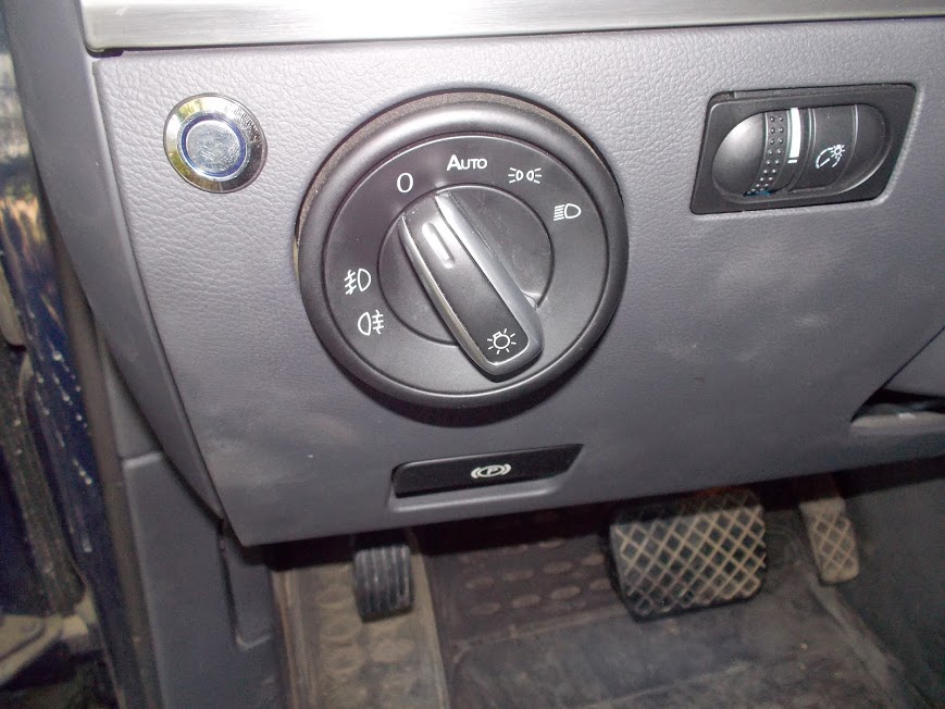

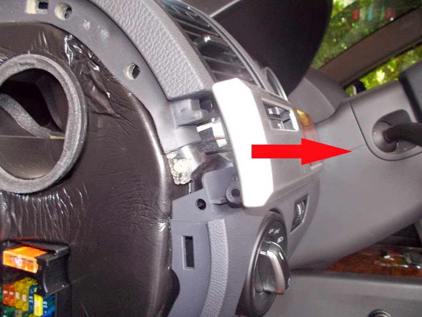
I made a 16mm hole for the button on the left hand side, near the light switch.
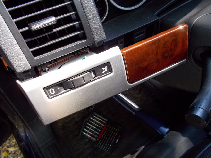
When assembling and installing the panel to the left side from the steering wheel, it is easier to first put the air shutter regulator into the panel, and then put the panel in place.
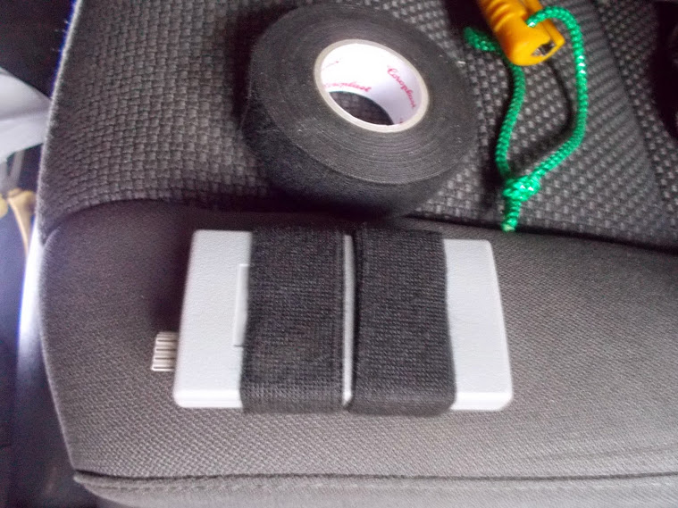
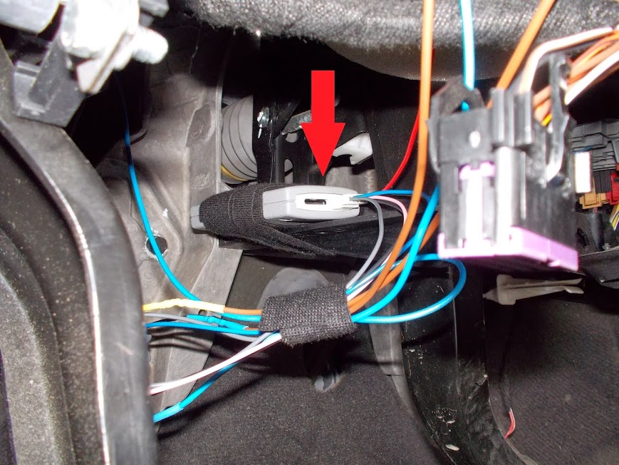
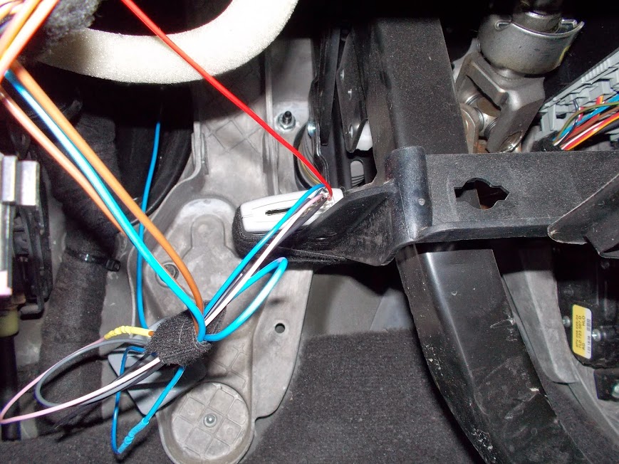
I put the Altox WBUS-4 GSM module on the bracket to the left from the brake pedal. In order to prevent shifting/rattling, I wrapped electrical tape around first.
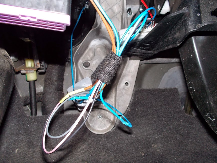
Keep all the wires together to avoid dangling.

After the installation, I checked if it worked. It did.The button has the blue light like the authentic lighting.
Pin assignment for the installation of the equipment.Altox WBUS-4 GSM module wires:Red - +12V from the fuse panel via the fuse 1АBlack - GND, taking from the upper mounting screw of the fuse panel (see above)Pink – for the button's contact N01Blue – the wire from Webasto moduleGrey – to the + contact of the buttonButton's contacts:+ OUT from the Altox module (gray)- GND, taking from the upper mounting screw of the fuse panel (see above)С1- +12V from the fuse panel via the fuse 1АN01 - Input KEY from the Altox module (pink)We express our gratitude to Alexey (ZAlek), the author of the report and a member of ClubTouareg.Ru.