Altox-Freelander2
Report from our customer on the installation of the Altox Wbus-4 GSM module to control Webasto module in a 2008 Land Rover Freelander 2
This photo report covers the upgrade and revamp of the default Webasto auxiliary heater for a 2008 Land Rover Freelander 2 into a full-featured starting pre-heater.All owners of diesel cars know very well that a pre-heater is highly needed in the winter season. At the same time, not many venture into the upgrade of the car with such useful equipment as Webasto heater GSM control module. Car manufacturers save money as well and the best that users can get in most cases is Telestart system.
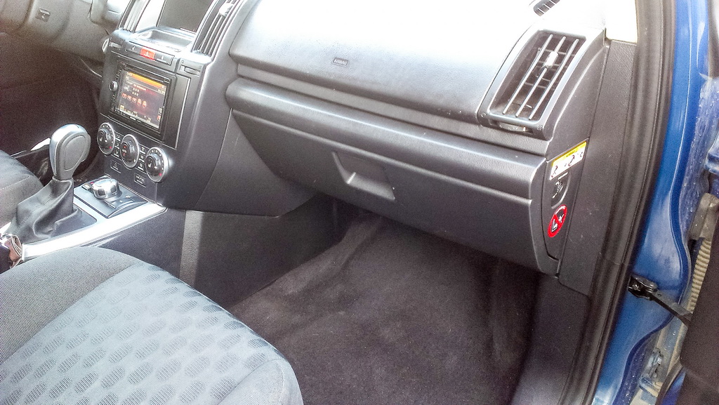
I will show now how to upgrade LAND ROVER Freelander 2 with such a great device.I have a 2008 model with Telestart installed after the manufacture.To install the ALTOX WBUS-4 module we should remove the glove box first.

To do that, push the retainers on the sides of the box inside.
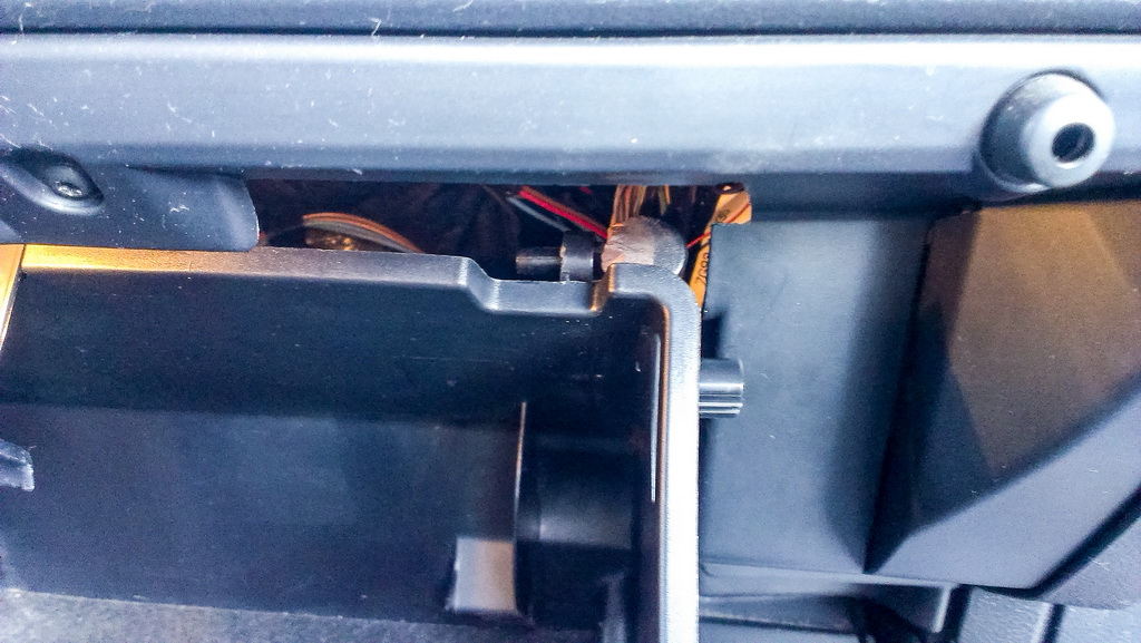
Now we remove a telescopic shock absorber of the box.
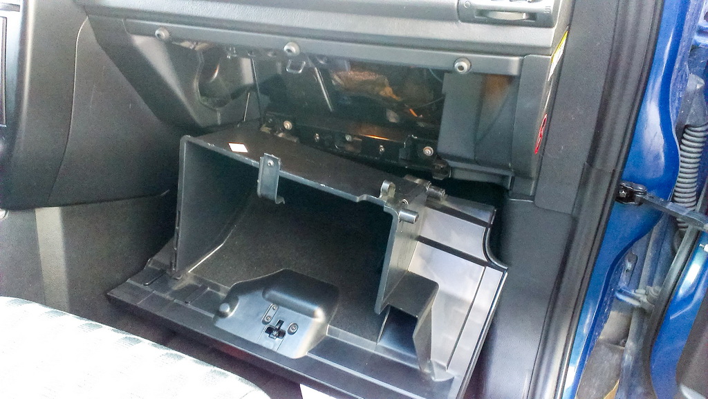
Open the box and pull it to remove it from lower rest slots.
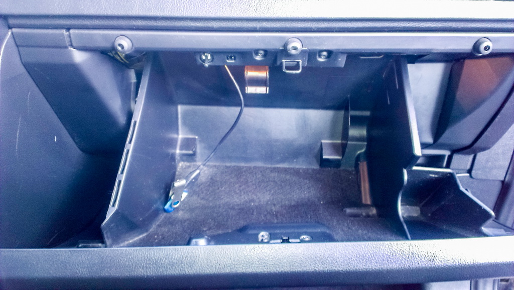
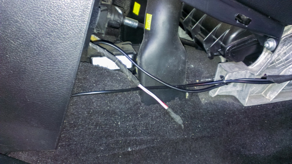
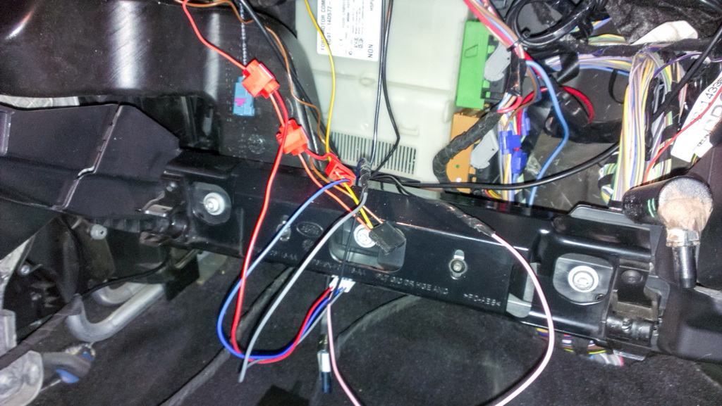
You will not see that many wires in your car. These are the wired from additional devices I equipped my car with, and since their manufacturers do not the same kind of promotion as ALTOX and WEBASTO, I can't tell you anything about them.
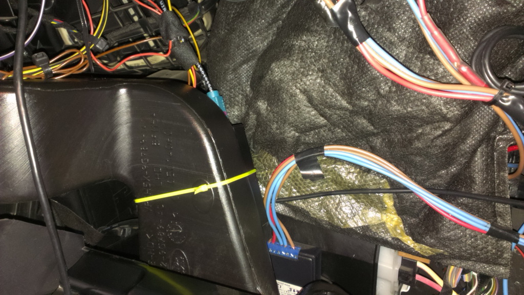
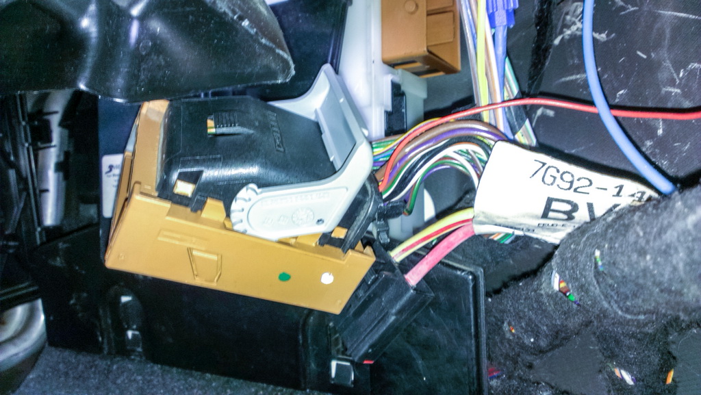
On the air duct to the left you see a yellow retainer – that's where Telestart is located (the original retainer was black). To connect ALTOX module it is enough to connect these three wires to the relevant slots. Telestart has supply + and - and WBUS wire that controls Webasto heater and that is needed for ALTOX.
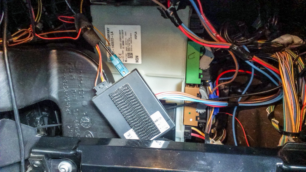
The module is glued to a special plastic sticky tape that secures it in place (the retainer is there for backup). Let's disconnect the module with wires and antenna's slot. We don't need Telestart module anymore.

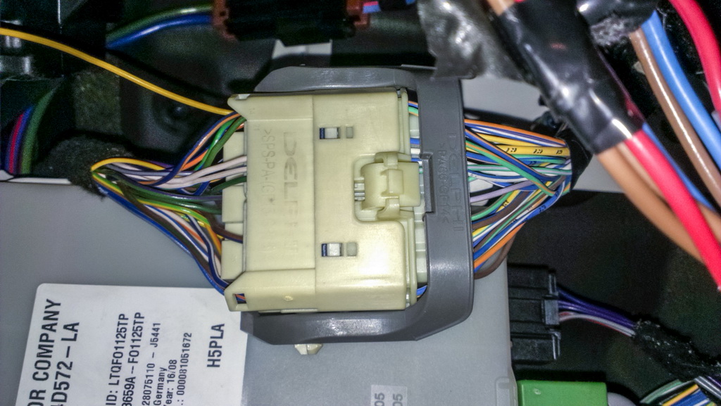
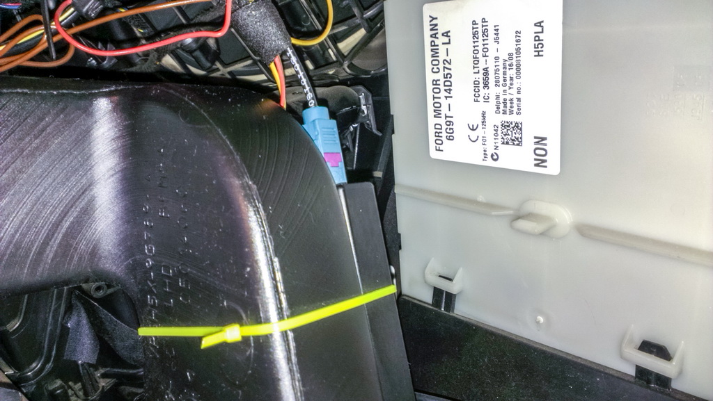
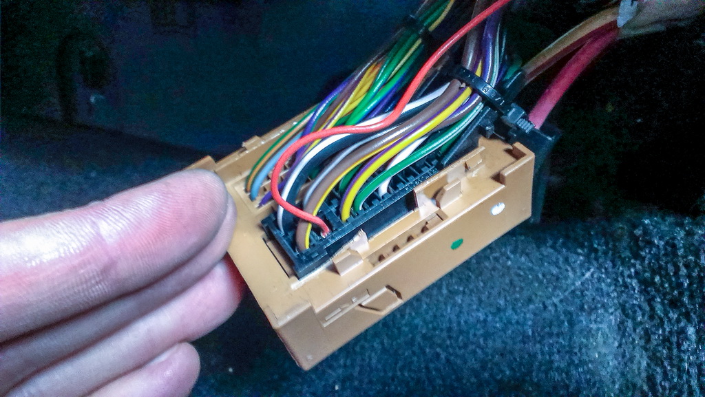
Telestart module wires and their colors: Red «+» (pin 1) Yellow WBUS (pin 2) Brown «-» (pin 6)If you have different colors, I will tell you how to easily identify the wires. Let;s start with WBUS. If we pull the decorative cover up, we will see a large CPU module (CJB), and above that at the very top you will see a large slot – that is where Telestart wire is connected. On the other side of the slot you will see a blue and white wire. If Telestart was not installed, then that is the only wire there. Obviously, you will not see the yellow wire there.
The brown wire goes to the left to the mounting spot. Everything is clear here.The red wire goes to the lower slot on the right hand side of the central processor.Before you start working with the processor wiring remember to remove terminal posts. LAND ROVER's electronics is very sensitive and if you don't want to get a huge amount of errors (or possibly more than just that) do not touch the central module's slots without cutting off the power first.It is already connected via a fuse but with a different nominal value, so we will connect Altox module using knife-blade terminal connectors. I use them all the time. With them you don't need any insulating tape. If there is no wiring or if Telestart was factory installed you should find a red + wire with the suitable length. It is important to make sure that this is a permanent plus wire, i.e. it does not switch off some time after key off. Alternatively, you can pull a wire from the back cigarette lighter but that is the option for when you can't find anything closer.

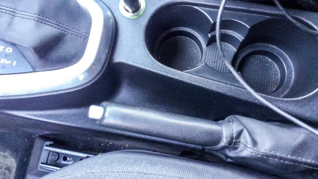
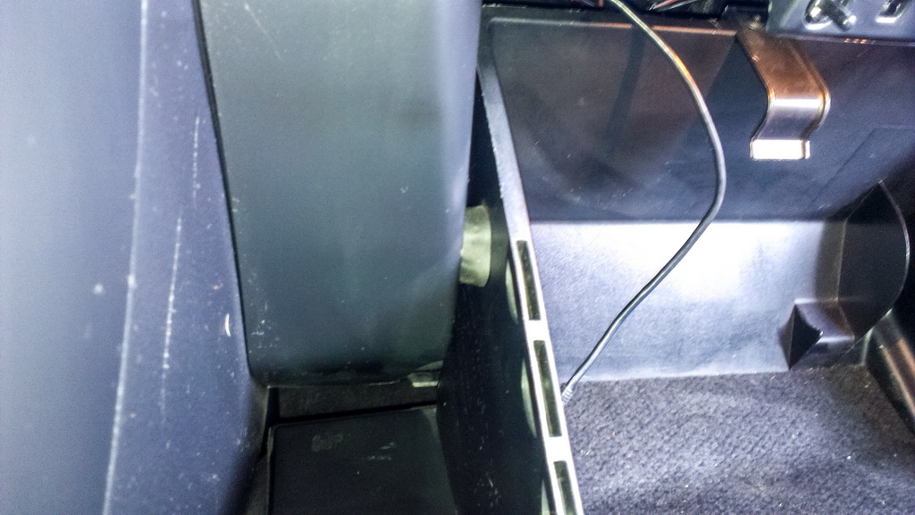
Now you have a place to put the button with an indicator. In the set there is a non-latching button with a built-in LED. The manufacturer did not provide in the manual information about wires application, and so I had to check them, just in case. Red plus (supplying to the same plus as the module)Black minus (to earth)Pink (when the button is pressed it sends plus to the module's KEY input, the color is matching)White (LED supply plus, it is supplied from the gray wire of Altox module)I chose the place for the button for some time because I did not want to have it in front of my eyes, but there was no point in hiding it either. I decided to put it in the tunnel near the handbrake – there is enough space there, it does not stand out, and the indication can be seen even from the driver's window.
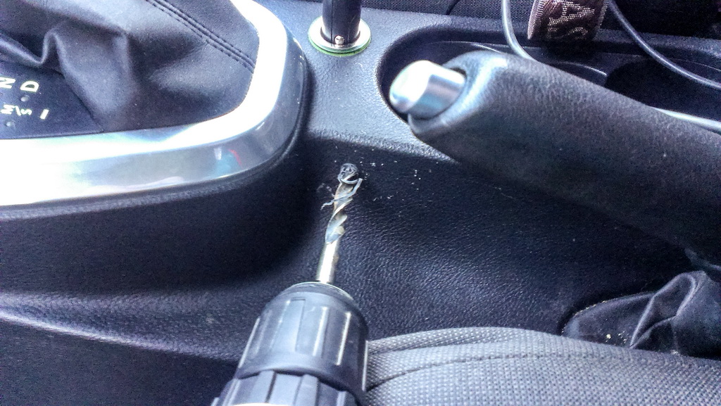
Let's move the driver's seat back and down to the maximum, so that the seat would not be in the way when we drill a hole. Using a screw gun at a low speed and a drill bit that is 8 mm in diameter make an opening in the place we have chosen. I used a wood drill with a special pen-type grinding. It is more convenient because it does not slide over plastic material. Then we remove the beveled edge with a large drill and if required even out the plastic material. If you are going to drill at a high rotating speed and push really hard, then the plastic will melt and it will require more effort to even out the edge.

Let's prepare the cable for the Webasto forced start button. To avoid rattling we wrap it with cloth electrical tape. It is tight now and won't dangle. I wrapped the ends of the wires for the convenience. It makes it easier to pull them through the tunnel. After that was done, I unwrapped them.
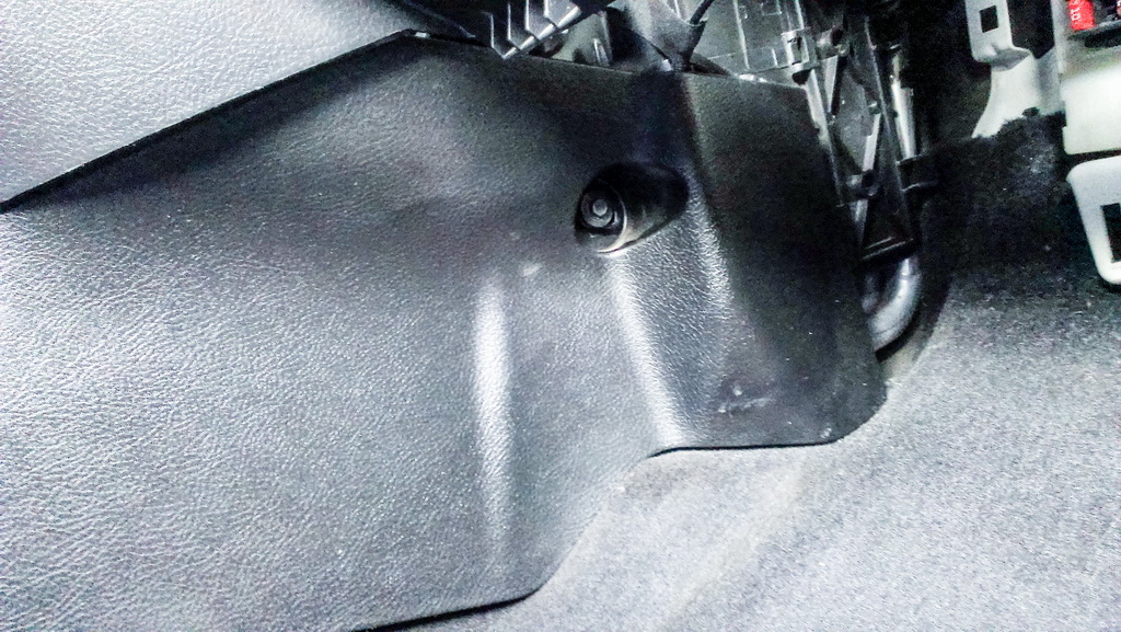
From the passenger's side, we remove the plastic cover that is held by a screw with a 7 mm screw head and two spring latches a little below the central console. After the screw is unscrewed, we pull the cover; the latches keep it in place from above.
We pull the wire directing it at the top to the left and pass the cigarette lighter unit. Then we get it through to the place where the cover will be installed. It was easy and we got it on the first try.

The button should be inserted until you feel it is fixed in the place. It gets through as if it was always there. We are done with mechanical works, let's move the electrical part.
Now we need to connect the button to the required sources. The wires are too short, so we should lengthen them. You can spin or seal them, there is a minimum current there, you should not give that too much thought but you definitely should remember to insulate the wires. If you use wires in other colors to lengthen your current wires, remember which is which, so that you don't have to check them again later.Now we connect plus wires of the button and the module with knife-blade terminal connectors to the red plus wire of the Telestart system.The minus wires of the button and the module will be connected to earth in any convenient place. I connected them to the safety bag mounting screw. I did not use the minus wire of the Telestart system. It was more convenient to connect to earth in a different place.The white wire of the button is connected to the gray wire of the module. The pink wire of the button is connected to the pink wire of the module.Finally, the blue wire of the module (WBUS) is connected via the terminal connector to the yellow wire of the dismantled Telestart system.

I found a rather good place for the module (you can even hide the GSM beacon) – behind the safety bag between the panel and tight hand side air duct. Above the installation place of ALTOX WBUS-4 there is only plastic material and the panel cover, a bit higher there is a windscreen. Mine is heated but I did not notice any significant impact.
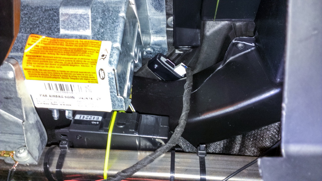
Before putting the module in place, insert a SIM card into it. You should be VERY careful when inserting the card. The SIM card slot is much longer and the space for the card is shifted to one side. Plus, the visibility is not the best, especially when it is darker. The card does not seem to want inside the slot – the flat side should face forward whereas the side with the cut should face the module's contact group. You should not push hard or you can damage the SIM card connector. If you are not sure if you are doing it correctly, you can disassemble the module and put the card in while seeing what you are doing.Let's check if we connected the module correctly, we power it up. The green LED will light up in the SIM card slot. After the connection is established, it will start flash on and off.I wrapped the module with an extra layer of tape to increase friction, even though it fits tight in there anyways.
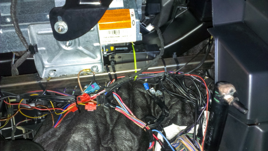
We use plastic retainers to keep all wires together. I wrapped the wires with cloth electrical tape in places where I anticipated possible squeaks. Here it is only up to you.
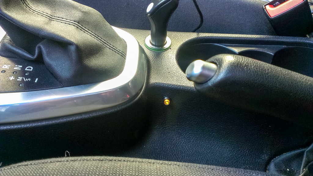
That's how the button lights up when the heater is started in the pre-heating mode. It is almost impossible to push it by accident.

I set up the device in accordance with the manufacturer's instructions. I set up the heater type as 5 just like for the Telestart system. I set up APN to control the module via Internet.
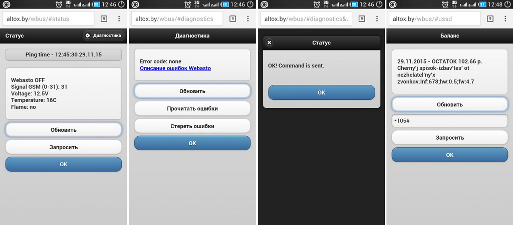
I waited for the correct conditions for the heater start up and checked everything step by step. Everything worked without any problems. I used the button, a voice call, a text message (SMS), and the web interface on Altox website (http://altox.by/wbus/) to start up the heater.
If it does not start up for you, check the power supply to the device and WBUS. The next possible issue might be that the conditions for WEBASTO start up on Freelander 2 have not been met, the coolant temperature should be lower than +15 C, the outside temperature should be lower than +5C, the engine has been at a stand-still for more than 30 minutes. These conditions are slightly different for different firmware versions, so you should check them at dedicated forums/. Another thing is that FL2 in a sleeping mode might calculate the outside temperature using the heater sensor because the sensor in the mirror does not work when the car is in a sleeping mode.I will also remind you that if you did not have the Telestart system installed in the car at all, then after the installation of the ALTOX module you need to activate the Telestart system in the car using the diagnostics cable (or dealer equipment) and SDD software. You can do it yourself or ask someone who knows what he is doing. If it is not done, the system will not work AT ALL.Tools used for the installation:- cutter (to remove old retainers and cleaning the wires);- electrical tape (thermal contraction tube);- cloth electrical tape (to avoid the squeaks);- knife-blade terminal connectors (I needed 3 pieces);- 7 mm screw head and a wrench or a screwdriver for that;- a screw gun or a drill;- an 8 mm drill bit;- a 10 mm wrench (to remove battery terminal posts);- soldering copper.I hope this report will help you with the installation of the ALTOX WBUS-4 GSM module in your LAND ROVER Freelander 2.